Bridge Truss Design and Analysis
Team Member, Group Structural Analysis Project
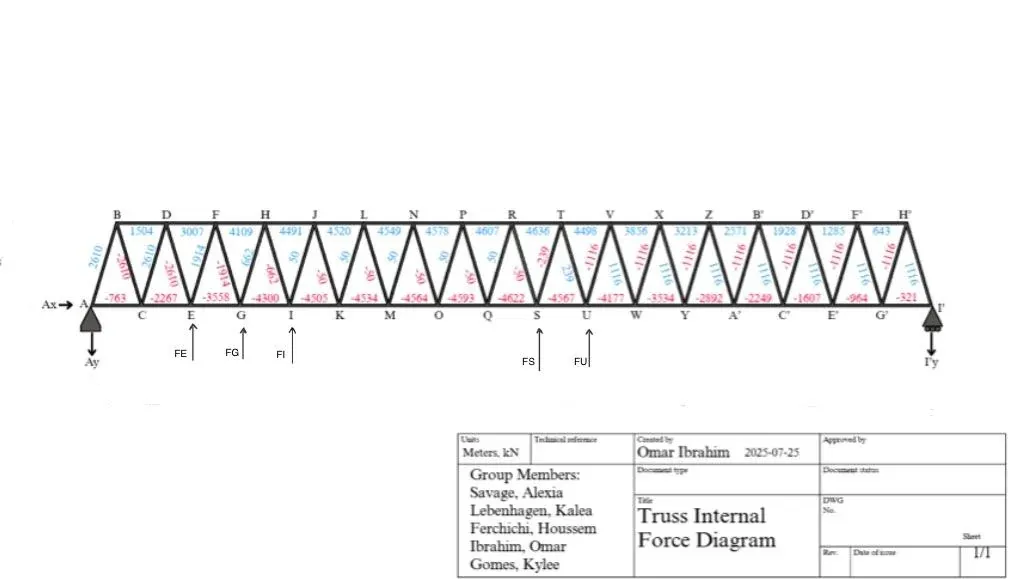
Analyzed the forces and reactions on specific truss support variations for a light rail bridge and determined the appropriate truss configuration.
Objective
To understand the loads applied to our chosen truss configuration so we could improve safety, reliability, cost, and simplicity while still supporting the structure and the train. We did this through truss analysis: calculating the live and dead load forces on the configuration to find the strength, cross-sectional area, and total force each member has to carry. The deliverable included the truss calculations, including stress and strain, and a formatted engineering drawing, so that if the design were ever used it would have the information needed to continue to construction.
Specifications and approach
The bridge spans 40.9 meters and is supported from above. The truss is pin-supported at one end and roller-supported at the other to allow for expansion and contraction. The load factor used is 1.5L + 1.25D, where L is live load and D is dead load, which gives a safety margin above the calculated maximum loads.
The first submission covered live load: the weight of the train and its passengers. The maximum load occurs when the nose of the train reaches 95% of the span, about 38.9 meters. The train has two cars of 392 kN each, with a distributed passenger load of 5.10 kN/m per car at full capacity. We set the bridge height at 4 meters, which satisfies the constraint of falling between span/12 and span/9, and spaced the members at 2.406 meters, giving 17 joints along the bottom chord.
The final submission added dead loads and internal force calculations. The dead loads include the rail (0.638 kN/m), rail ties of normal-density concrete (23.5 kN/m³) measuring 180 mm x 250 mm x 2.7 m at 500 mm on center, and W350 steel beams and stringers. Each beam has a cross-sectional area of 7610 mm², a length of 3 meters, and a dead load of 0.580 kN/m applied at each panel point. Two stringers span the bridge, each with a cross-sectional area of 6650 mm² and a dead load of 0.513 kN/m. From these we calculated the distributed dead load across the span and the point load at each joint. Comparing the options, a Warren truss without verticals was the best choice for function and efficiency.
Outcome
Our group chose a truss based on the specifications and the resulting support reactions to support the light rail train while keeping cost and complexity down. We then calculated stress, strain, and deformation, and recalculated the member forces with the dead load included. Those results showed that the tension members needed to change to W410x60 sections, while the compression members could stay as HSS89x89x9.5. By the end of the project we had a plan to build the truss to our specifications with the efficiency and stability we were aiming for.