Designing Next-Generation Electrolytes for Solid Oxide Fuel Cells
Co-researcher on a two-person team (authors contributed equally): equation derivation, computational structure building, and poster presentation
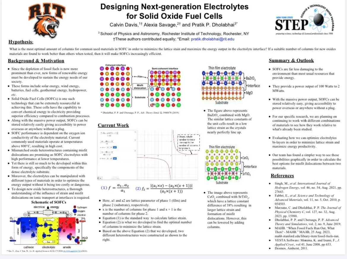
Derived a strain-minimization equation that reduced CeO2/SrTiO3 interface lattice strain from 27.82% to 3.76%. The work took 1st Place at NYS STEP Regionals and a Gold Medal at the 2024 Zimbabwe Science Fair.
Objective
Solid oxide fuel cells (SOFCs) convert chemical energy directly into electricity with water as the by-product, but commonly used electrolyte materials operate above roughly 800 C, which raises cost and limits where the cells can go. Thin-film electrolytes built from mismatched oxides promise strong performance at lower temperatures; the catch is the interface. When a CeO2 film (5.41 A unit cell) is layered on a SrTiO3 substrate (3.905 A), the size difference produces 27.82% lattice strain and misfit dislocations that hurt ion transport. Our research question: how many columns of each material make the crystals line up best?
Approach
During the RIT STEP research program (2023-2024), mentored by Prof. Pratik Dholabhai of RIT’s School of Physics and Astronomy, our two-person team started from the standard lattice-strain formula f = (a1 - a2)/a1 and derived a new equation, f2 = |(a1·x) - (a2·(x + 1))| / (a2·(x + 1)), where x is the number of film columns and x + 1 the number of substrate columns. Graphing it in Desmos turns column selection into a readable problem: the whole number nearest the x-intercept gives the optimal column count for the larger unit cell, and the smaller cell takes one more. We then built the corresponding heterostructures computationally in VESTA to confirm the atoms line up at the interface. Both authors contributed equally to the derivation, the structures, and the poster.
Outcome
We aimed at ensuring that before SOFCs are researched in a lab to determine which materials give the greatest efficiency, they can be studied computationally to save time and money. The best materials and column combinations for effective ion transport can be found with software and mathematical models, so that when the cells are designed and tested in a lab the work can focus on the options the simulations and mathematics already point to. For CeO2 on SrTiO3, three columns of CeO2 over four columns of SrTiO3 reduced lattice strain from 27.82% to 3.76%, and the same method applied to BaZrO3 on MgO confirmed an already well-matched pair at roughly 0.04% strain.