Design and Build

Ping-Pong Ball Launcher

A flywheel launcher with a servo-fed gate, designed, drawn, built, and tested by a four-person team

2026 · AERO 2001 Aerospace Graphical Design · Carleton University · Group 7 (four students)

Group member: CATIA modeling, the drawing set, the build, and the report
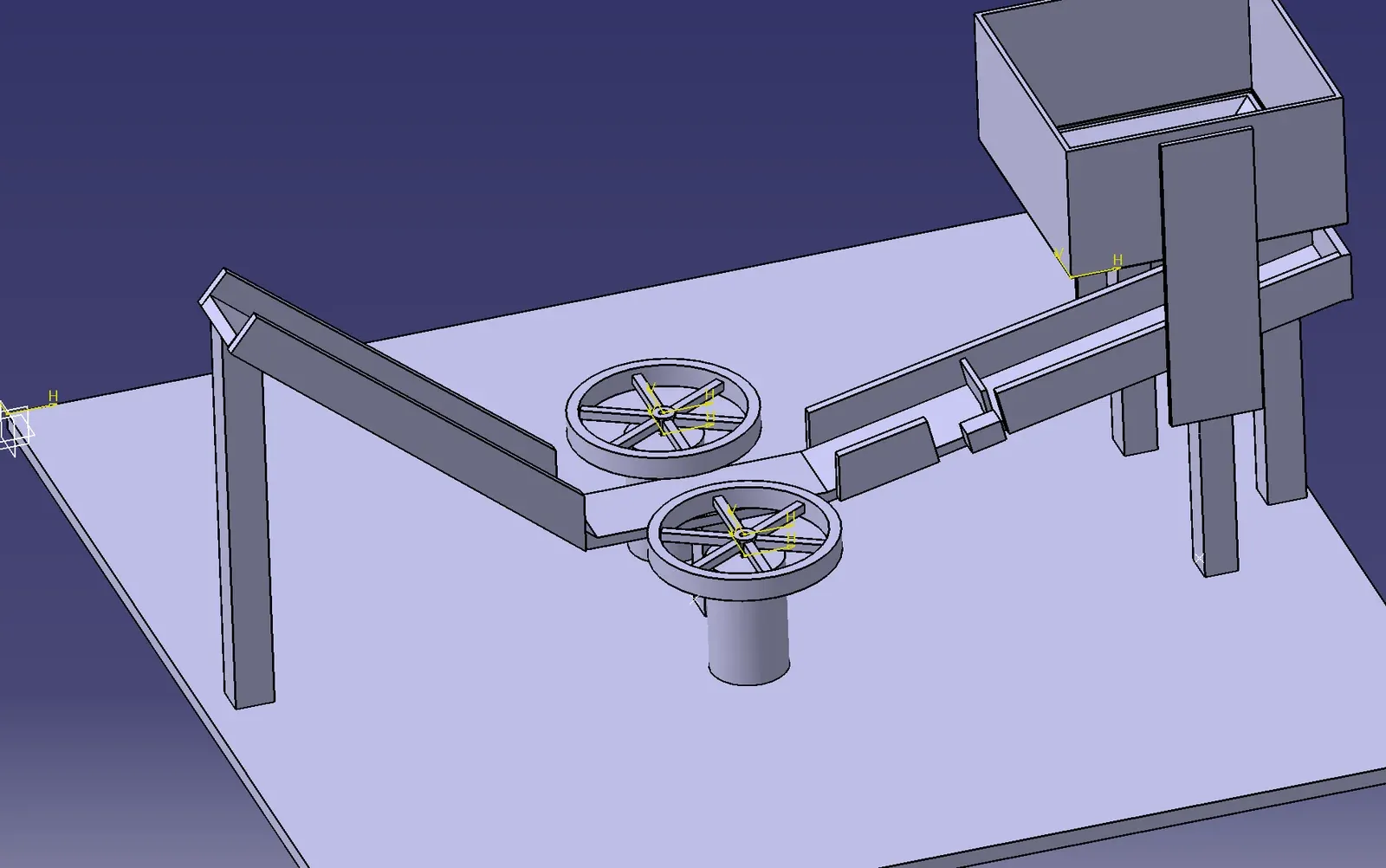
CATIA isometric view of the ping-pong launcher assembly: a funnel bucket on a stand feeding a ramp, two flywheels on motors at the end of the ramp, and a net, all mounted on a square base plate
Result

An Arduino-timed flywheel launcher that fed and fired all 20 balls in 26.5 seconds of the 60 allowed without jamming. Height and range consistency were the weak points, and the report sets out what we would change.

Objective

Design and build an automated system that shoots 20 ping-pong balls from a starting square, through a 6 x 6 inch opening in a barrier, and into a bucket in a target square, in under 60 seconds. The system had to fit within 2 ft x 2 ft, stand no more than 1 ft off the ground before starting, run on no more than 12 V, and cost no more than $100.

How it works

A 12 V supply powers an Arduino and a pulse-width-modulation controller in parallel. The Arduino drives a servo that opens a door at the bottom of the ball reservoir for 0.325 seconds, closes it, and waits one second, so balls feed one at a time on a 1.325 second cycle. Each ball rolls down a ramp into two spinning flywheels, which launch it toward the target. A potentiometer on the PWM controller lets us adjust the flywheel speed by hand to tune the exit velocity for the opening height and the range to the bucket.

The frame, ramps, and supports are wood held with hot glue, the reservoir is cardboard, and the flywheels and door are 3D printed in PLA. Rubber bands on the flywheels gave the grip the smooth printed surface did not have.

Outcome

The feed mechanism worked as intended: all 20 balls cycled through in about 26.5 seconds without a jam. The manual speed control made it possible to adjust for the required height and range on the day. The problems were consistency of height and trajectory. The two motors were not perfectly aligned, so the balls did not follow the calculated path, and raising the speed to reach the opening height tended to overshoot the bucket.

If we did it again we would add an adjustable ramp angle so speed and angle could be tuned separately, close in the ramp so the ball path is constrained, and orient the flywheels parallel to the ramp so the ball is not slowed by hitting the ramp after launch.

Figures

The finished build: reservoir and servo door at the back, ramp to the two flywheels, and the Arduino, motor controller, and battery on the base.
The built launcher on a bench: a cardboard reservoir on a wooden stand feeds a cardboard tube and ramp down to two red 3D-printed flywheels, with the Arduino, PWM controller, and battery pack wired on the OSB base

The finished build: reservoir and servo door at the back, ramp to the two flywheels, and the Arduino, motor controller, and battery on the base.

The servo-driven door that releases one ball at a time.
Close-up of the 3D-printed red door at the bottom of the cardboard tube holding back an orange ping-pong ball, with the small blue servo that opens it mounted beside the ramp

The servo-driven door that releases one ball at a time.

The two flywheels, with rubber bands on the rims for grip.
Top-down view of the two red 3D-printed flywheels with rubber bands around their rims, each mounted on a DC motor, with the ramp between them and the Arduino to the side

The two flywheels, with rubber bands on the rims for grip.

Assembly drawing with top, front, right, and isometric views at 1:6 scale.
Assembly drawing 7 of 7 of the ping-pong launcher on an A3 sheet at 1:6 scale, with top, front, right, and isometric views, balloon callouts for the six parts, and a Carleton University title block naming Alexia Savage as drawn by and designed by

Assembly drawing with top, front, right, and isometric views at 1:6 scale.

Flywheel working drawing.
Working drawing of the 3D-printed flywheel with top, front, right, and isometric views and dimensions

Flywheel working drawing.

Servo motor and door working drawing.
Working drawing of the servo motor and door assembly with top, front, right, and isometric views

Servo motor and door working drawing.

The Arduino code for the door: one ball every 1.325 seconds.
Arduino sketch that opens the servo door for 0.325 seconds, closes it, and waits one second, giving a 1.325 second cycle per ball

The Arduino code for the door: one ball every 1.325 seconds.